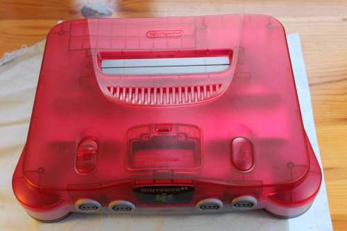
Guide for installing the N64RGB into all models of Nintendo 64
Note: This guide is for version 1.1 and 1.2 hardware (marked N64RGB11 or N64RGB12).
Tools and materials required:
- Soldering iron and solder wick.
- Screwdrivers - Philips and Nintendo head.
- Sharp pair of side cutters.
Click on the pictures to make them bigger.
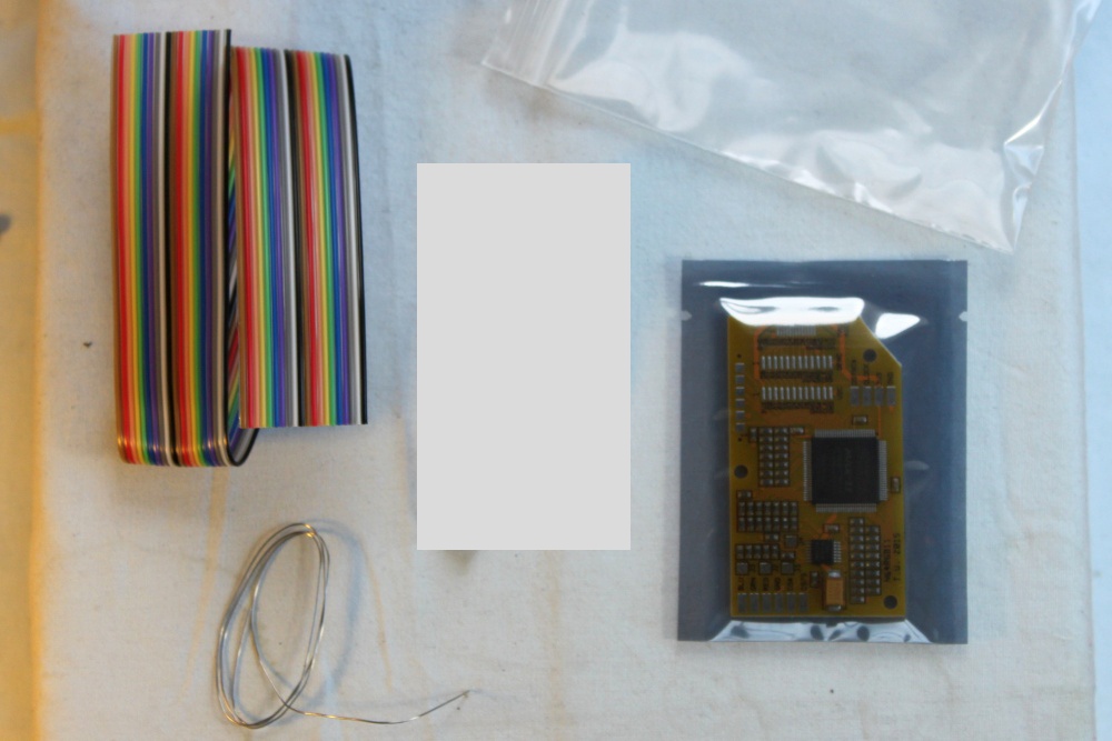 |
The following parts are included with the kit.
|
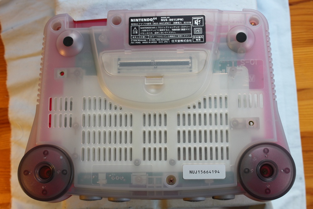 |
Start by removing six Nintendo head (gamebit) screws from the base of the console. |
 |
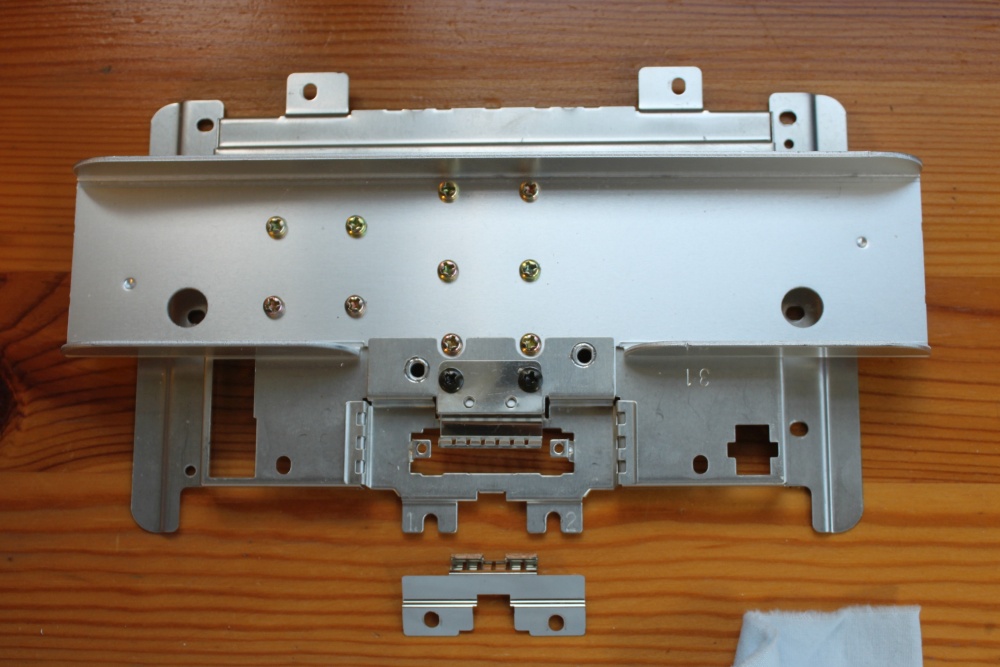
Inside the motherboard is protected by a large RF shield/heat sink assembly. The weak points are circled. |
 |
Off in (almost) one piece. |
 |
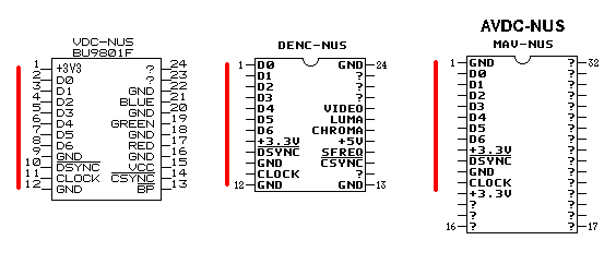
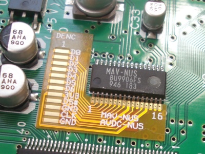
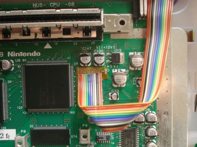
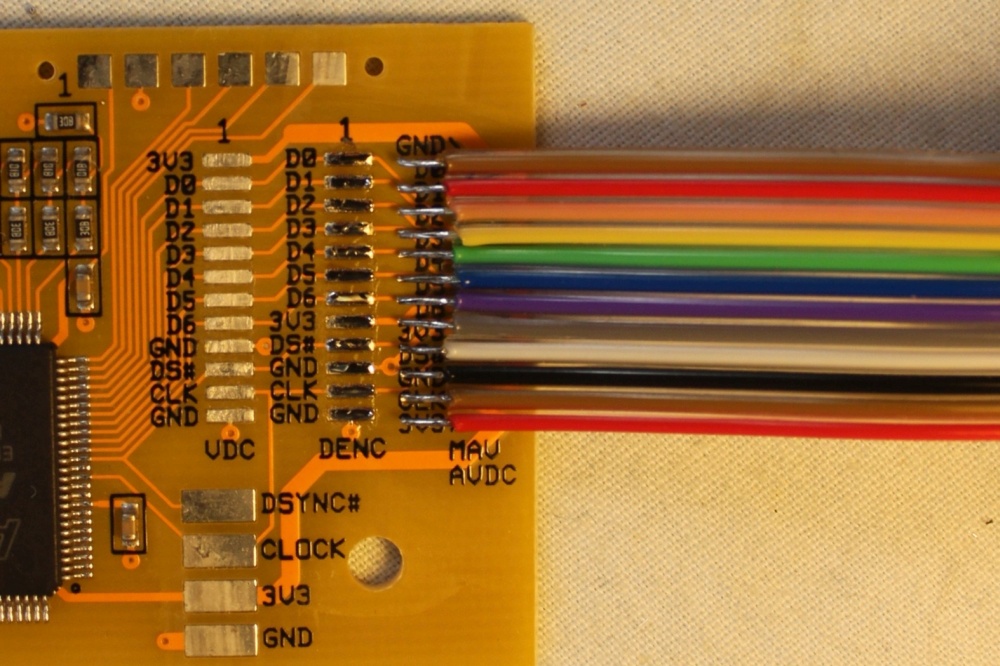
The large IC in the centre of the motherboard is the graphics
processor. Immediately to the right is the video encoder/DAC.
There are four different types: DENC-NUS, VDC-NUS, AVDC-NUS,
MAV-NUS. With the latter two being the same for the purposes of
this installation. The signals D0-D6, DSYNC# (DS#), CLOCK (CLK) carry the digital video data into the N64RGB board. 3V3 is for power and GND is the return path for all signals. The DENC-NUS and VDC-NUS chips have a pin spacing of 1.27mm. The AVDC-NUS and MAV-NUS chips have a pin spacing of 0.8mm. |
 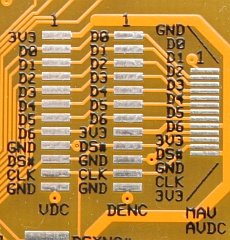 We will use the ribbon cable to
connect the signals from the motherboard to the N64RGB board.
If your Nintendo 64 console has a DENC-NUS or VDC-NUS chip then jump to Input Wiring Method #2. Otherwise, it has a AVDC-NUS or MAV-NUS so read on. |
|
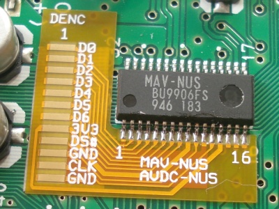
Consoles with MAV-NUS and AVDC-NUS which require the
pin adapter.
Consoles with the MAV-NUS and AVDC-NUS type of DAC chip require the pin
adapter for easy installation.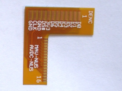 |
The adapter transforms the MAV-NUS/AVDC-NUS pin arrangement @
0.8mm pitch to the DENC-NUS pin arrangement @ 1.27mm pitch. |
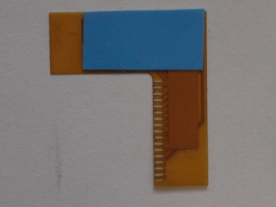 |
There is some double sided tape stuck to the back. Remove the blue film. It's thin and rated for high temperature. |
 |
Stick the adapter down. Make sure it sits right up against the vertical edges of the DAC chip's pins. |
 |
Solder the adapter to the pins with the (included) fine solder. Extra flux is not essential, but may be helpful. |
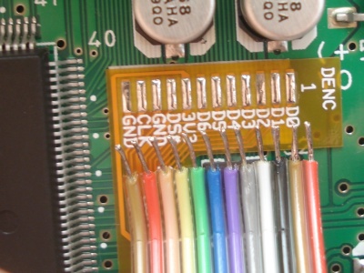 |
Strip the wired on the ribbon cable and tin the ends with solder. Tin the DENC pads on the adapter. There are some detailed instructions for stripping the ribbon cable further down the page. |
 |
To solder the ribbon to the adapter, just place each tinned wire
over the tinned solder pad and apply some heat with the soldering
iron. Take note which colour wire is on pin 1. |
 |
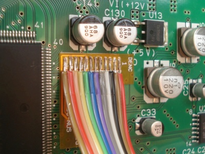
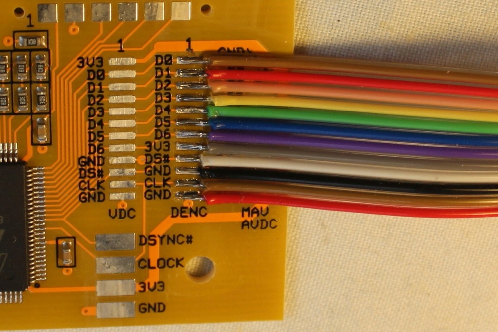
Arrange the ribbon cable as shown. |
 |
Solder the other end to the DENC pads on the N64RGB board. It's
quite easy, just apply pressure with the soldering iron to each
wire in turn. Wait for the solder joint to cool before soldering
the next one. Now the input wiring done. Jump to Finishing Off. |
Consoles with VDC-NUS and DENC-NUS chips.
 |
The ribbon cable has a wire spacing of 1.27mm. This matches the
pin spacing of the VDC-NUS and
DENC-NUS chip, as
well as the pad spacing on the N64RGB board. Here's how to prepare it. |
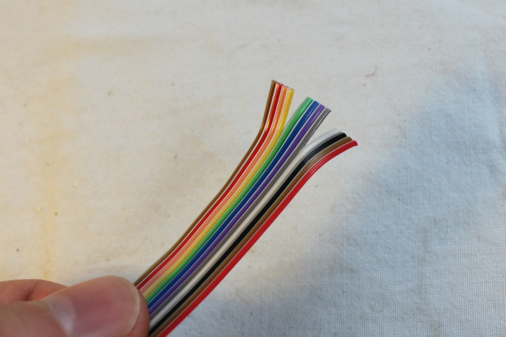 |
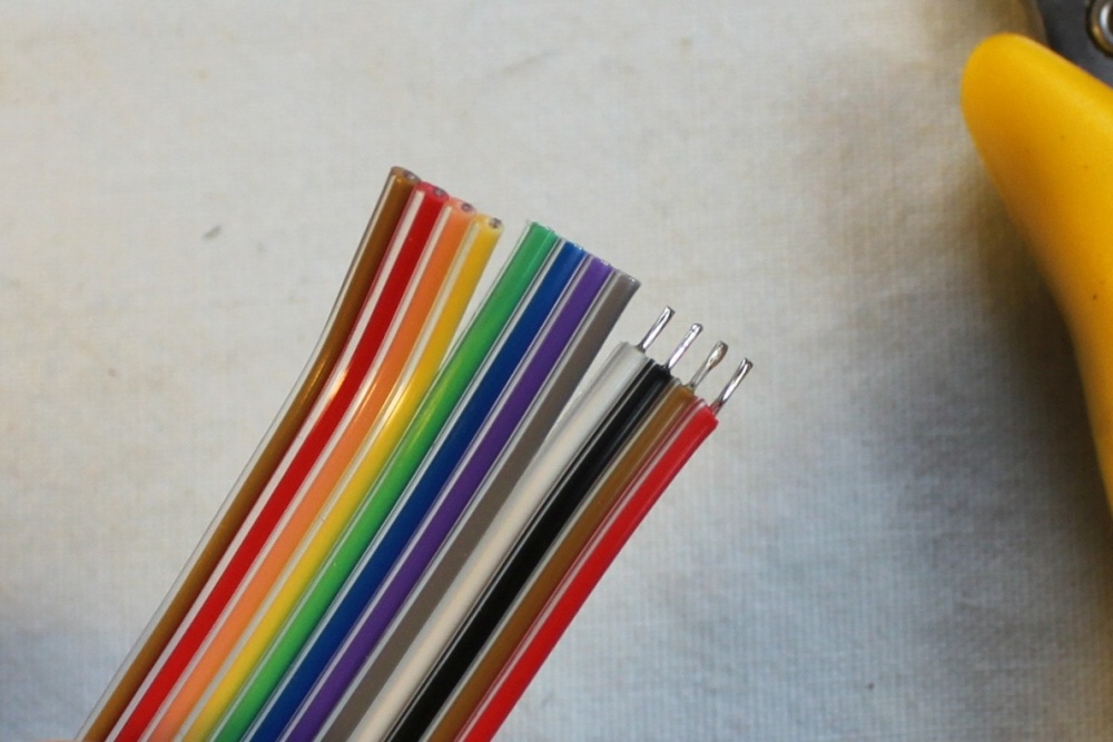
Separate the end into three groups of four wires. |
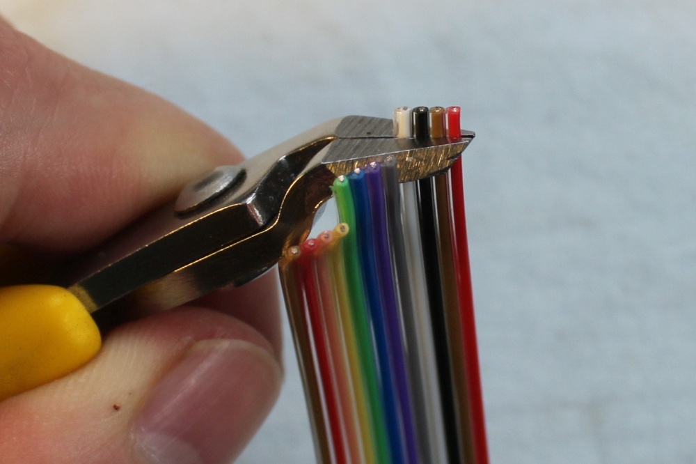 |
Strip the insulation off the end of the ribbon cable. This should be as easy as it looks. Cut through the insulation with the side cutters an pull. All wires are stripped at once. |
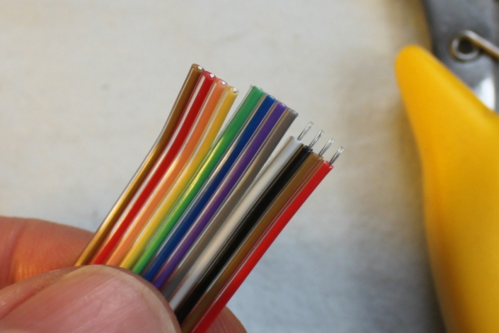 |
Insulation removed. |
 |
Tin the wires with solder. |
 |
Repeat for the other wires and the other end of the cable. |
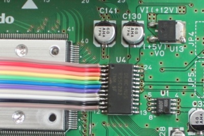 |
Add some extra solder to pins 1-12 of the DAC. Solder the 12 pin ribbon cable to the chip. Take it easy, one wire at a time. Move the wire over the pin, apply pressure with the soldering iron. You can use a pair of tweezers to wiggle the wire and make sure it's stuck down. If it's not, try again. Solder wick is good for removing excess solder. Take note which colour wire is on pin 1. Ignore the missing wire on pin 12 of this picture. |
 |
Bend the ribbon cable like so. |
 |
Tin the either the VDC or DENC solder pads on the N64RGB board (depending on which DAC you are connecting to). In this case it's the DENC. |
 |
Solder the wires to the board. It's quite easy, just apply
pressure with the soldering iron to each wire in turn. Wait for
the solder joint to cool before soldering the next one. Now the input wiring done. Jump to Finishing Off. |
Using your own wire.
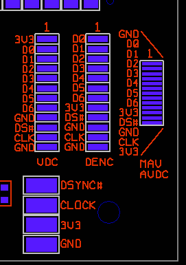 |
You may prefer to use your own wire to connect the input signals. If so, please do not attempt to solder you own wire to the MAV/AVDC solder pads. They are too small and there is no need to do this. All signals are available on the larger VDC and DENC solder pads. Also, you are welcome to make use of the large pads for DSYNC# (DS#), CLOCK (CLK), +3V3, and ground (GND). I recommend at least two ground wires for a more reliable operation. Keep wires to 300mm. |
Finishing Off
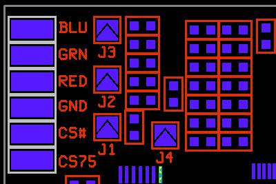 |
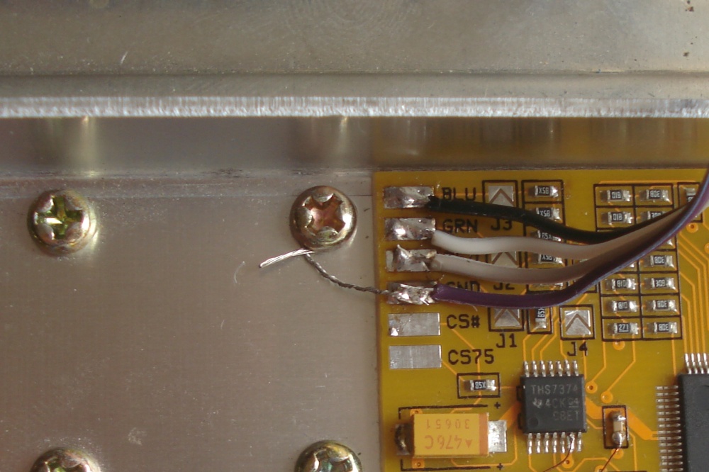
Here's the output section of the N64RGB board. The pads are BLU - Blue video. GRN - Green video. RED - Red video. GND - Ground. CS# - Composite Sync TTL. CS75 - Composite Sync 75 ohm. Jumpers J1, J2, J3 select the cable type
|
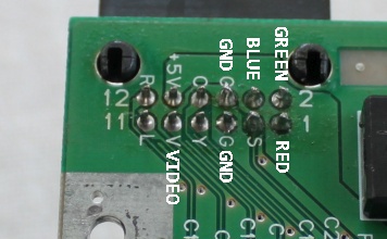 |
A standard installation has four wires soldered between the
N64RGB board output pads and the Nintendo A/V output socket. Red,
Green, Blue, Ground. Use the extra wires from the colourful ribbon
cable. The original composite video signal is normally used for sync. Some people claim this causes a small amount of interference to the RGB video (particularly with cheap cables). There are two ways to solve this problem.
|
 |
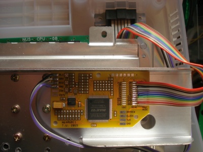
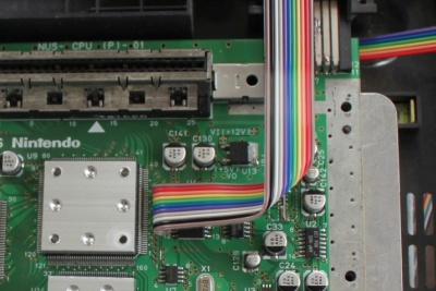
Now it's a good time to test the installation. Don't run the
console for more that a few minutes without the heat sink
attached. (Please ignore the old style data cable in the photo) |
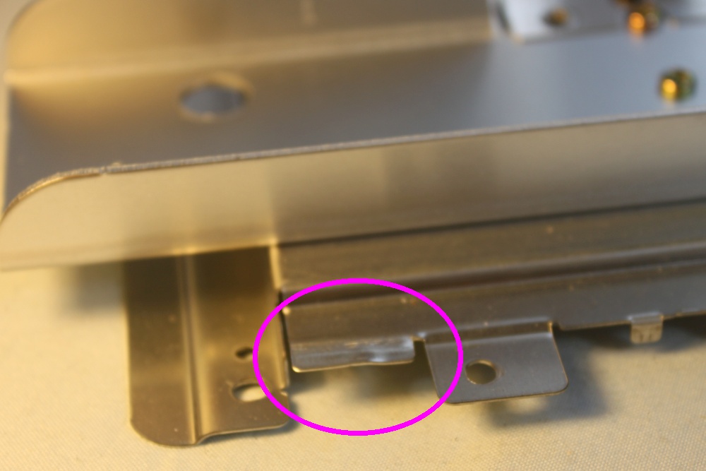 |
Before putting the heat sink / RF shield assembly back on, bend
this tab out so the ribbon cable may pass through. |
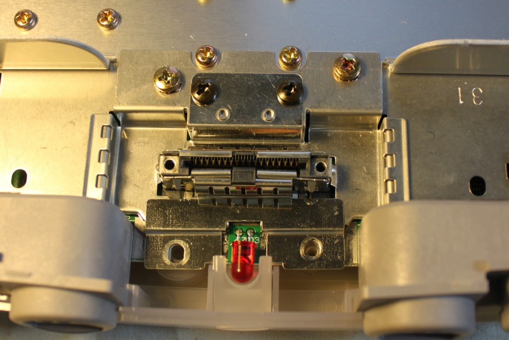 |
The are a pair of small tabs that sit either side of the memory
expansion slot. Make sure they are fitting in place correctly when
re assembling. |
 |
There is some adhesive tape on the back of the N64RGB board.
Once the heat sink / RF shield assembly is in place and screwed
down, peel the blue plastic off and stick the board down as shown
in the picture below. The corner of the board is cut off to allow
access to the screw under the heat sink. The tape is designed for higher temperature environments and will not degrade with heat like ordinary double sided tape. |
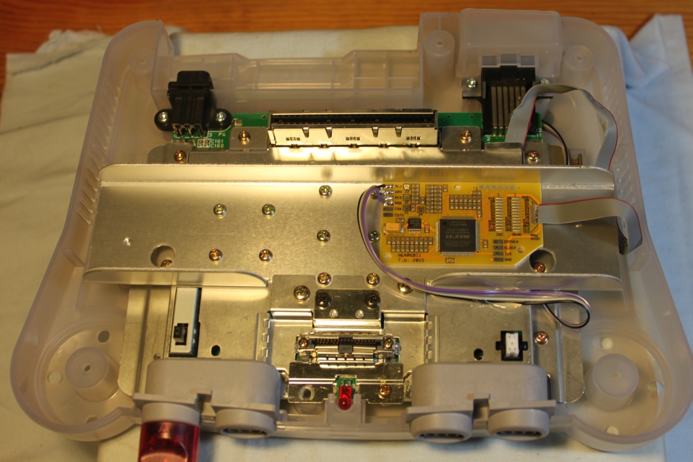 |
The N64RGB board is stuck to the heat sink. It's best to keep
the analog video output wires away from the digital input wires. (Please ignore the old style data cable in the photo) |
 |
The final step is to make a good connection between the N64RGB
board's ground and the motherboard ground. The heat sink/shield is
directly connected to the motherboard ground all around the edge
so we'll use it as a ground point. Strip about 30mm of insulation from a piece of wire and twist the strands together. Solder the end of the wire to the ground pad of the N64RGB board. Unscrew the heat sink screw which is closest to the wire. |
 |
Wrap the stranded wire once
around the neck of the screw clockwise
and screw it back down. Make sure the wire has some slack and does
not break when tightening the screw. That's it. Put the top half of the shell back on and the installation is complete. |
Change Log
13/3/2017 - Added final step of connecting the gound to the heatsink. This should solve the vertical line interference that some people have been experiencing.
8/6/2016 - Added new wiring information relating to the new adapter for fine pitch DACs. Removed obsolete fine pitch cable wiring details.
9/10/2015 - Rewrote the guide entirely, including extra details about wires and soldering.
18/2/2015 - Added some details about V1.1 hardware.
11/10/2014 - Page created.